
Foundation Excavation and Earthworks
From Plan to Quantity Takeoff
september 2026
Foundation excavation is a critical part of construction. Excavating to the specified depths, dimensions and levels provides the space needed to build the foundations. Calculating these quantities accurately helps contractors, estimators and quantity surveyors price the work and plan how it will be carried out.
A foundation drawing may look straightforward, but the earthworks takeoff can quickly become more involved. Ground beams and pile caps may sit at different depths, access areas need working space, and sloping excavation sides increase the volume beyond the concrete footprint. Then there’s the backfill to calculate.
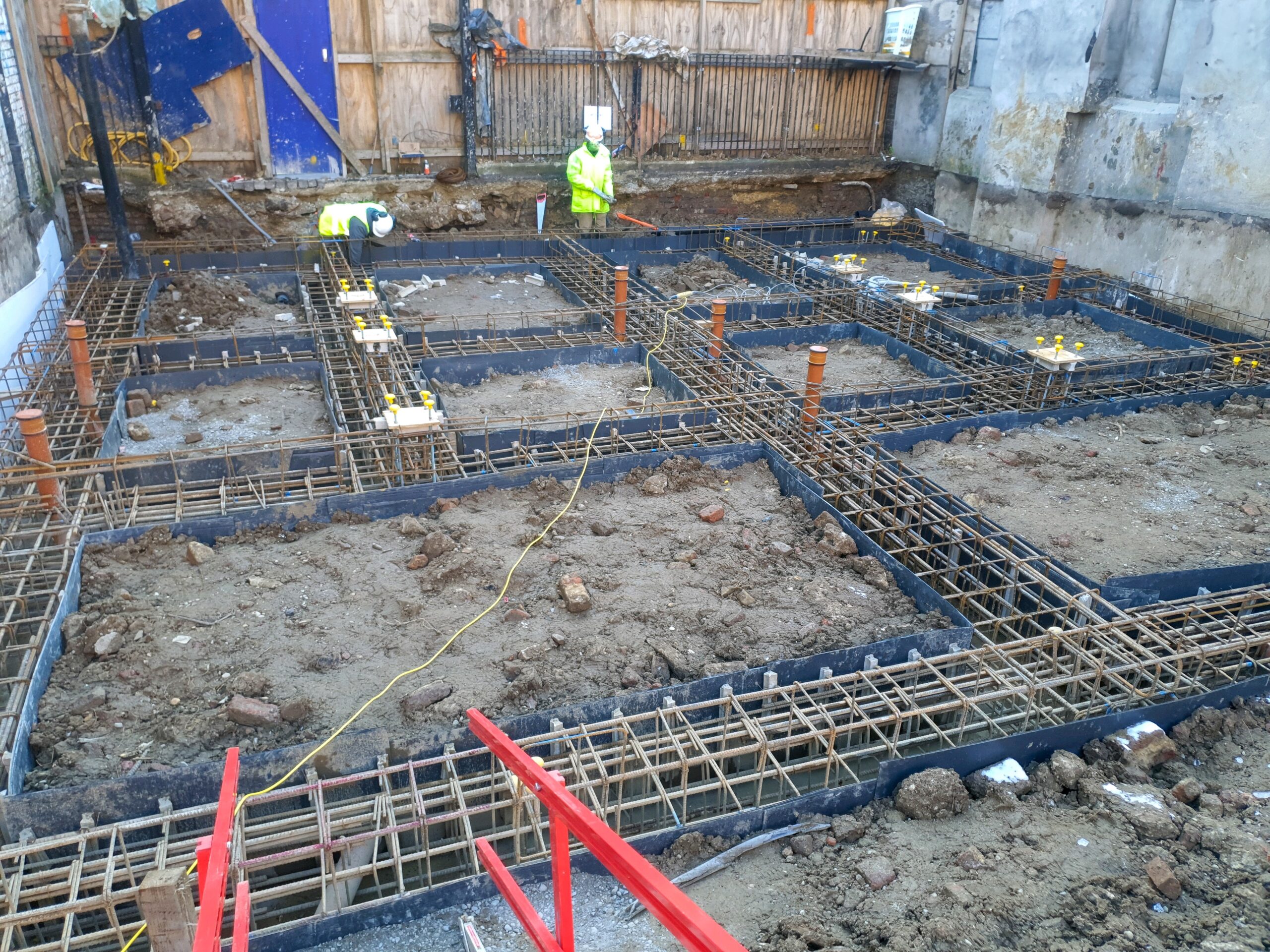
Digital earthworks modelling can simplify this process by turning construction drawings into a 3D model that can be used to calculate excavation, concrete and backfill quantities.
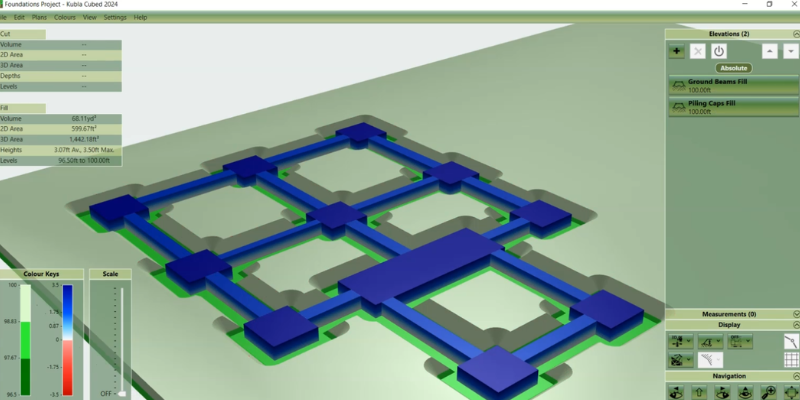
In Kubla Cubed, a practical approach is to build the excavation from simple, overlapping elements, then use construction phases to account for concrete and backfill. This guide follows Kubla Software’s Building Foundations tutorial, showing how to capture that detail without tracing every junction individually.
Read the plans before building the model
Before importing anything, work out how the foundation excavation fits together. Identify the ground beams, pile caps, footings and access areas etc. along with their dimensions and levels.
Check whether the drawing specifies a depth below ground, which is relative or an elevation measured from a fixed datum, which is absolute. This distinction affects which modelling element you use.
Also check the excavation limits. The concrete footprint alone may not include working space or side batters, both of which contribute to the excavation quantity.
Tip
Understand Elements and Phases Before You Start
The most useful concept in this workflow is the difference between combining elements and progressing through phases.
Elements within the same phase combine to create one proposed surface. Where they overlap, elements lower in the list override those above them. They do not represent successive excavation or filling operations.
Step 1: Import Site Plan & Check the Scale
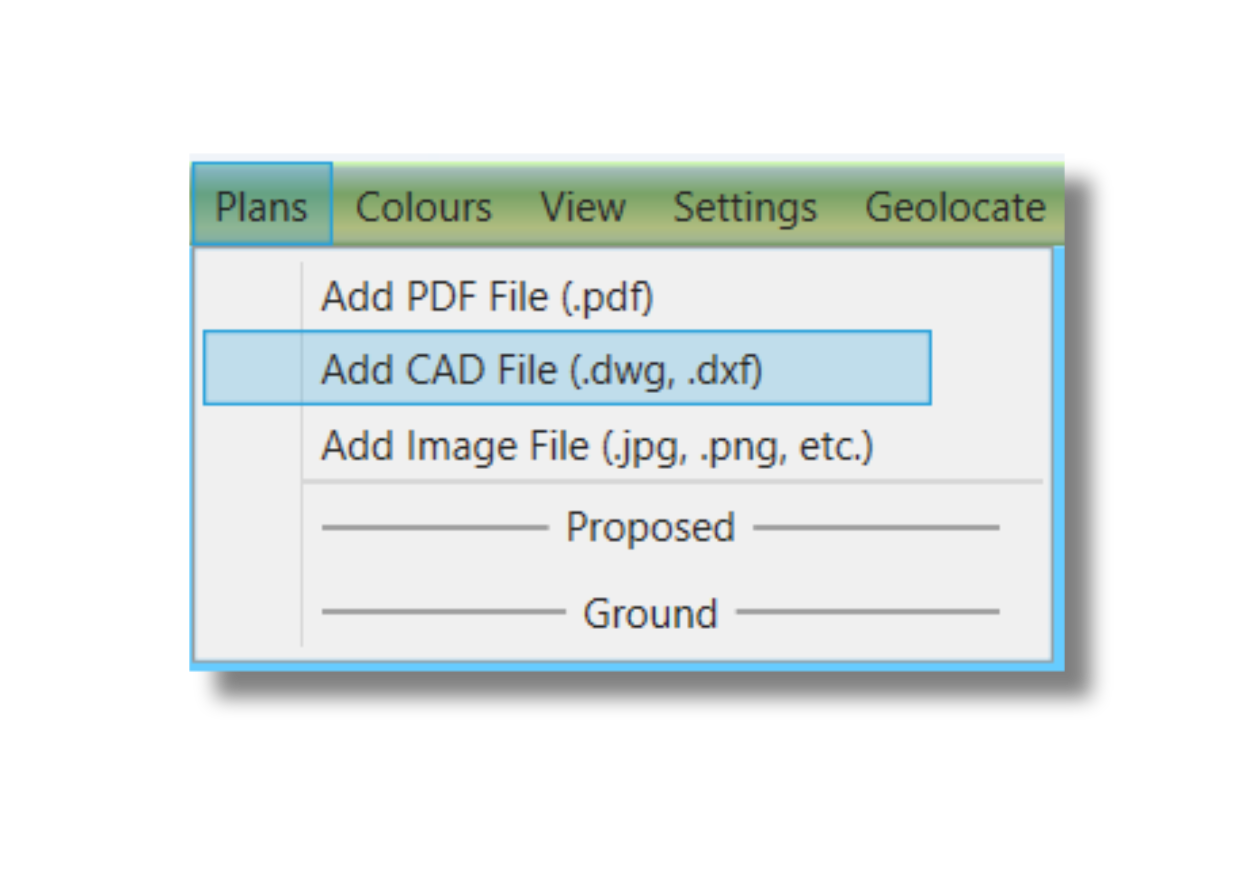
Use the Plans menu to add your PDF, CAD drawing or image. The tutorial uses a PDF and demonstrates scaling from a known dimension.
T/race from one end to the other of a known line and enter its length.
Where Kubla Cubed suggests a nearby standard scale, check it against the drawing before accepting it.
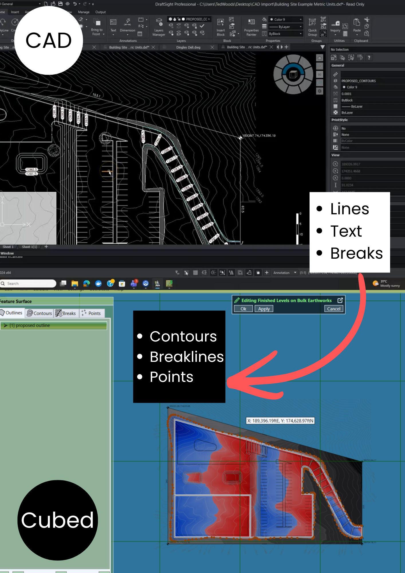
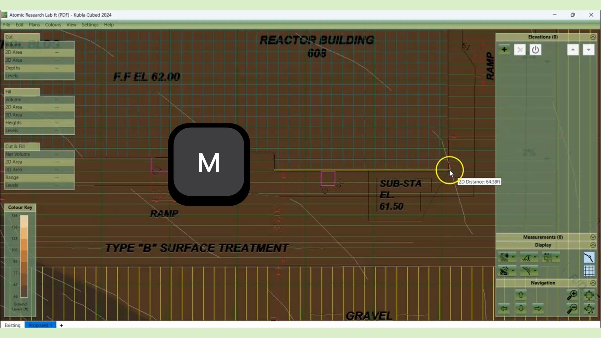
Next, hold down the M key to measure a known distance. This is a quick way to confirm that the plan is correctly scaled ready for tracing/importing data. CAD files are usually scaled correctly but not always. It’s also worth checking the units as the insertion units in CAD are often unreliable.
It’s a small check worth doing before any tracing. A model can look convincing in 3D even when the underlying plan is incorrectly scaled.
Tip
If the scale is wrong here, everything that follows in your project will be wrong too. It’s really worth getting this right from the start.
Step 2: Establish the Starting Ground
The demonstration adds a Feature Surface with a flat surface with an elevation of 100 feet. This arbitrary level keeps the example simple and makes the excavation depths easy to follow.
For your own project, use the ground surface applicable to the foundation works. If the site has already been graded, that may be the surface produced by an earlier construction phase. Foundations excavated after bulk grading, for example, should be measured from that graded surface.
Step 3: Choose Reduce or Platform
Once the existing ground has been established, the next step is to define the main excavation area. Depending on the project, this could be a general foundation excavation, working area or access walkway.
Move to the next construction phase and give it a clear name, such as Foundation excavation.
In Kubla Cubed, a Reduce element lowers the starting surface by a specified depth. A Platform defines a surface at a specified elevation.
Use Reduce when the drawing gives a depth below ground. For example, an access or safety walkway could be reduced by 1.5 feet from the existing ground level.
Use Platform when the excavation must reach a fixed formation level.
On sloping ground, this choice matters: a constant reduction follows the starting surface’s slope, while a level Platform creates a flat base.
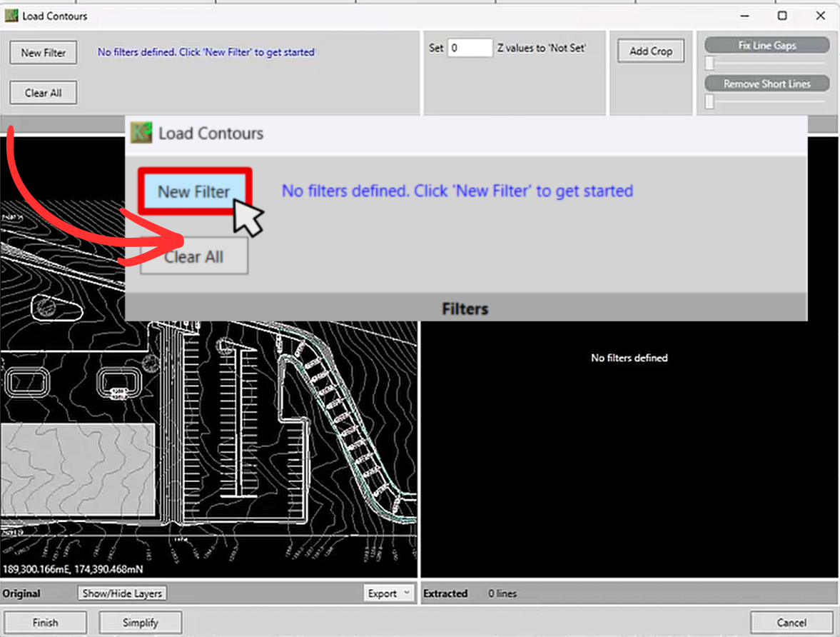
Step 4: Build the Excavation from Simple Shapes
The tutorial combines three Reduce elements:
- An access walkway around the foundations.
- Ground beams excavated below the walkway.
- Pile caps extending below the beams.
Each has its own depth and outline. Their order determines the finished excavation where they overlap.
Define the Access Area First
Start with the broader excavation footprint for the access walkway. You don’t need to trace around every beam and pile cap, because those elements will override it later.
To leave internal areas unexcavated, draw closed outlines inside the outer boundary. Kubla Cubed recognises these enclosed outlines as holes within the same element.
The example walkway uses a depth of 1.5 feet and a 1:1 side batter. Enter the dimensions and batter requirements specified for your project.
Add Ground Beams and Pile Caps
Create another Reduce element for the ground beams. Trace the beams continuously through the pile-cap positions instead of stopping and restarting at each intersection.
Then add the pile caps as a separate element below the ground beams in the list. Their excavation will override the beam excavation where the shapes overlap.
Use copy and paste (Ctrl+C and Ctrl+V) to duplicate identical outlines to reduce repetitive work. Check dimensions before reusing a shape, particularly where the plan contains similar-looking components.
Check Side Batters and Element Order
Side batters affect the excavation volume, so include the required slopers as well as its plan outline (footprint).
The video uses a 1:1 batter for the access walkway and demonstrates a 0.01 setting as an approximation for near-vertical sides on the foundation elements. These are example modelling settings; use the excavation geometry specified for your project.
Give each element a clear name as you work. “Ground beams” is much easier to recognise later than a list of unnamed Reduce elements. The inspect the model in 3D and turn on element colours to check the overlaps.
Step 5: Create a Separate Concrete PhaseSeparate Phases
Once the excavation is modelled, the next question is how much of that space will be occupied by concrete—and how much will remain for backfill.
This is where construction phases become useful. We recommend this phase sequence:
Existing ground → Foundation excavation → Structural concrete → Backfill
No Image Carousel Cards Found!
Please add image carousel cards and setup the data
Each phase starts from the surface produced by the preceding phase. By contrast, elements within a single phase combine to create one proposed surface.
Adding concrete to the excavation phase would therefore alter the excavation model, rather than represent the next stage of construction.
Step 6: Reuse the Excavation Boundary for Backfill
You can trace the backfill boundary manually but reusing the excavation geometry can save time on more involved layouts.
The tutorial demonstrates this through a CAD export:
- Open File → Export CAD Data.
- Select the foundation excavation phase.
- Enable Include Cut/Fill Lines, removing unnecessary export options.
- Save the file, then create a separate Backfill phase.
- Import the relevant closed boundaries into a Platform and set the required backfill level.
The example is entirely excavation, so its cut lines describe the disturbance boundary. Review the imported outlines before accepting them.
With the concrete already represented in the preceding phase, the backfill calculation measures the remaining space up to the specified level.
Step 7: Check the Model and Understand the Report
Before using the quantities, inspect the model in 3D. Look for missing components, unexpected overlaps and excavation edges that don’t match the drawing.
Use the elevation cursor to check depths at representative points. Cross sections through a beam, pile cap and adjoining access area can also help confirm the levels. Each phase compares its starting surface with its combined proposed surface.
Finally, review the spreadsheet export. Where elements overlap, the overriding element receives the cut or fill contribution for that area. A pile-cap quantity therefore includes the excavation beneath its footprint, rather than just the extra depth below the beam.
Final Thoughts
Efficient foundation modelling in Kubla Cubed starts with simple shapes and a clear construction sequence.
Check the plan scale, use overlapping elements to build the excavation, and separate concrete from backfill through phases. This keeps the model manageable and makes the quantities easier to check, revise and explain.
Ready to Explore?
Building Foundations FAQs
Key take aways from the video and article
▼ What information do I need for a foundation earthworks takeoff?
You’ll need the foundation layout, excavation depths or formation levels, and the ground surface you’re excavating from. Check for working space, side batters, concrete dimensions and backfill levels, as these also affect the quantities.
▼Should I use Reduce or Platform to model foundations in Kubla Cubed?
Use Reduce when the excavation is specified as a depth below the starting ground. Use Platform when it needs to reach a fixed elevation. On sloping ground, Reduce follows the underlying surface, while a level Platform creates a flat formation.
▼How does Kubla Cubed handle overlapping foundation elements?
Within a phase, elements lower in the list override those above them where they overlap. They combine into one proposed surface; their excavation depths do not add together. The overriding element receives the cut or fill contribution for the overlapping area.
▼ Why should concrete structures and backfill be modelled in separate phases?
Separate phases represent successive stages of construction. Modelling concrete after excavation establishes the space occupied by the structure before backfill is calculated. Adding everything to one phase would combine the elements into a single proposed surface.
▼ Why do side batters affect foundation excavation quantities?
Sloping excavation sides extend beyond the base footprint, increasing the volume of material to remove. A takeoff based only on the concrete dimensions can therefore underestimate excavation. Include the side slopes and working space specified for the project.