Adding Features from a PDF/CAD File
To extract vector data from a CAD.PDF file in Kubla Cubed:
- Adding the PDF/CAD File as a Site Plan:
- Open Kubla Cubed and navigate to Plans → Add PDF File (.pdf) or Add CAD File (.dwg, .dxf).
- Choose the desired PDF/CAD file and click ‘Open’.
- Scaling and Positioning the PDF File:
- Since PDFs are in printer space, you must scale and position the file as required.
- Use the Kubla Cubed tools to adjust the scale and position of the PDF accurately. SeeSetting the Position and Cropping.
- CAD files are usually scaled; however, a quick scale check by holding down the 'M' button is recommended. See Quick Measure Tool.
- Selecting Elements and Adding Features:
- Click + button in Elevations and select elevation element type you wish to add.
- Choose the feature tab (Outlines, Contours, Breaks, Points) for importing.
- Click the 'Add from File' button located at the bottom-left of the editor panel.
- Select the embedded PDF file you previously added as a site plan.
|
Upon selecting a CAD (.dxf, .dwg) file or vector PDF, a "Load.." pop-up window will appear (shown below). Please note that this window will exclusively extract features interpretable as the selected feature type, as follows:
|
- A new "Load..." window will open, click ‘New Filter’ ①.
The CAD importer allows multiple selection filters. This means that if you have major and minor contours you can have a filter for each rather than combined. Instead of filtering red and green lines with a width of 1 or 3, you can filter red lines with a width of 1 and green lines with a width of 3. This allows for more precise filtering.
- Position the cursor in the Original window ⑦, left-click to start and finish highlighting the element you wish to import.
- The selected lines/points will display in the ‘Extracted’ window ⑧. The number of points extracted displays in grey and the if there are points/lines with no defined value the count will show in red.
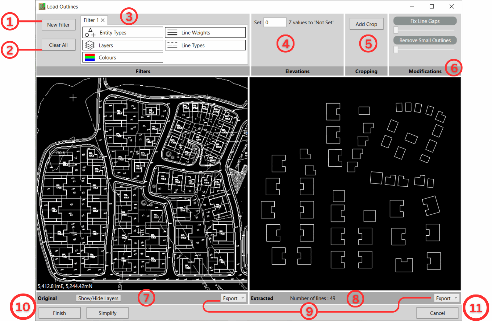
5. Inspecting and Filtering Options:
- ③ Filter: Inspect and filter entities in the site plan file by clicking on the Layers, Entity Types, Line, Weights, Line Types and Colours. Toggle on/off as needed; turned-off Layers etc. will not be imported.
- ④ Elevations: for setting elevations in CAD to a proxy ‘Not Set’ value (e.g -9999 or 0) which will then be converted to ‘Not Set’ when imported into Kubla Cubed.
- ⑤ Cropping: Only want to extract part of a site plan? Crop an area in the Original window to remove any unwanted data.
- ⑥ Modifications: Adjust the sliders to remove small outlines\lines and fix line gaps in the extracted data.
- ⑦ Show/Hide Layers: Click to see a list of layers in the file. Toggle on/off to show/hide the layers you require. This makes locating a specific layer easier to find.
- ⑧ Entity Status Display: Displays the total
number of extracted entities, including a breakdown of entities with levels and those without
levels based on the current Elevations settings as detailed in bullet point ④. Use the checkboxes to toggle the inclusion of
entities with levels and entities without levels in the output.

- ⑨ Export: Export the original file as a CAD file or Export the extracted data as either CAD or CSV.
- ⑩ Simpify: With large data sets, you can opt to reduce the detail by clicking the simplify button and adjusting the tolerance slider in the pop-out window.
- ⑩ Finish: Click once ready to import the data showing in the extracted window. This will close the window and show the data in the model view.
- ⑪ Cancel: Click to close the window without importing data.
6. Editing Entities in the Model View
After clicking Finish in the 'Load...' window, your entities will import into the Kubla Cubed model window where you can edit further.
- Outlines, Contours, and Break lines can be edited using tools found in the Tool Menu (Hammer/Spanner).
- Use these tools for Joining, Splitting, Setting Multiple Elevations, and Ordering features. Refer to Editing Tools for details.

|
Learn to import contours, points, and a poly-face mesh in our Working with CAD Data (.dxf, .dwg, .dgn) video, which also covers CAD export. |