The Elements Panel
Each phase in a project contains an 'Elevations' panel. This is where earthworks elevation elements such as Platforms, Slopes, Paths and Feature Surfaces can be added to the project. The Elevations elements in a panel are combined to create a single proposed surface within a single phase.
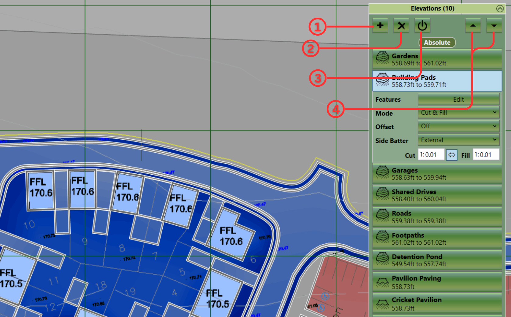
Elevations Element Panel
① Add a new element - This opens the Element Menu.
② Delete an element - Deletes the selected element from the project.
③ Disable and Enable an element - Excludes or includes the element from the volume calculations.
④ Move an element in the calculation order - The arrows move the elements up and down the order.
Adding Elements
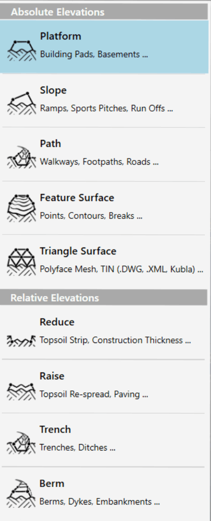
New elements can be added to the 'Elevations' panel by clicking on the + symbol ①. You will be presented with the following list of elements that you can add:
|
|
Once you have selected an element you will be able to start drawing its boundary or centreline points in the design area. Left-click to place a new point, Right-click or press Enter to complete the creation of the element. If you want to cancel the operation entirely, hit the Esc key. When adding new elements the Backspace key can be used to undo the last placed point if a mistake has been made.
Renaming Elements
After an element is created, it is a good idea to give it a relevant name so it can be identified in the report (e.g. Building Pad 1 or Car Park). To do this just double click on the name of the element and then over-type.
Editing Elements
- Selection : Elements can be selected by left-clicking on the title bar in the earthworks panel or by left-clicking on there boundary or centre lines in the design area. Multiple elements can be selected by holding down Ctrl whilst making the selection. To deselect an element you can right-click on it.
- Edit Mode : If you double click on an element it will enter into 'edit mode', the properties of the element will be exposed and you will be able to edit the definition points of the element in the design view. To exit 'edit mode' double left-click in empty space in the design view.
- Definition Points : When an element is in 'edit mode' the definition points of the boundary or centreline can be changed. In the design view left-click on a point and drag it to the desired position. A point can be deleted by using the Delete key. New points can be inserted by selecting a line and hitting the Z key. Points can also by edited directly in the point list in the element properties. Clicking on the top-left corner of the point list allows all the points to be copied using the menu command or Ctrl+C. Likewise a list of points can also be pasted into the point list from another program by clicking on the top-left corner and using menu paste command or Ctrl+V.
- Notes on Point Snapping : When creating or editing the definition points of a earthworks element it is possible to snap the points to other element definition points or to defined grid positions. To access the point snapping options click on the Edit menu and then the Snap Points. Here you can toggle snapping to boundary points and grid points as well as setting the interval and origin point of the grid used for snapping.
Properties
For information on the individual element properties refer to the relevant sections for each element.
Amending the Calculation Order
Copying & Pasting
It is often useful to copy and paste elements, this can be done using Edit menu commands or the keyboard shortcuts (Ctrl+C, Ctrl+V). You can copy and paste in the same phase to duplicate an element or copy and paste to move elements to different phases. See Copy and Paste.
Deleting Elements
Elements can be deleted by first selecting them and then clicking on the X button at the top of the Elevations panel ②. (image above)
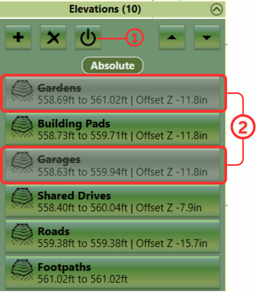
Disable and Enable Elements
|
|
Elevation Elements can be toggled between enabled and disabled by first selecting
them and then clicking on the power symbol button at the top of the panel ① (left). Disabled elements are greyed out and
have their names struck through ② (left).
|