To edit individual elements of the channel you can select the lines and points of the channel definition line. The selection box will display the selected start point, end point, straight section or bend of the channel. Properties which are calculated by the software will have an Auto button which indicates that the software is calculating this property and the input box will be disabled. If you want to override the values the software has calculated you can de-select Auto and type into the box.
The controls for channel elements are described below.
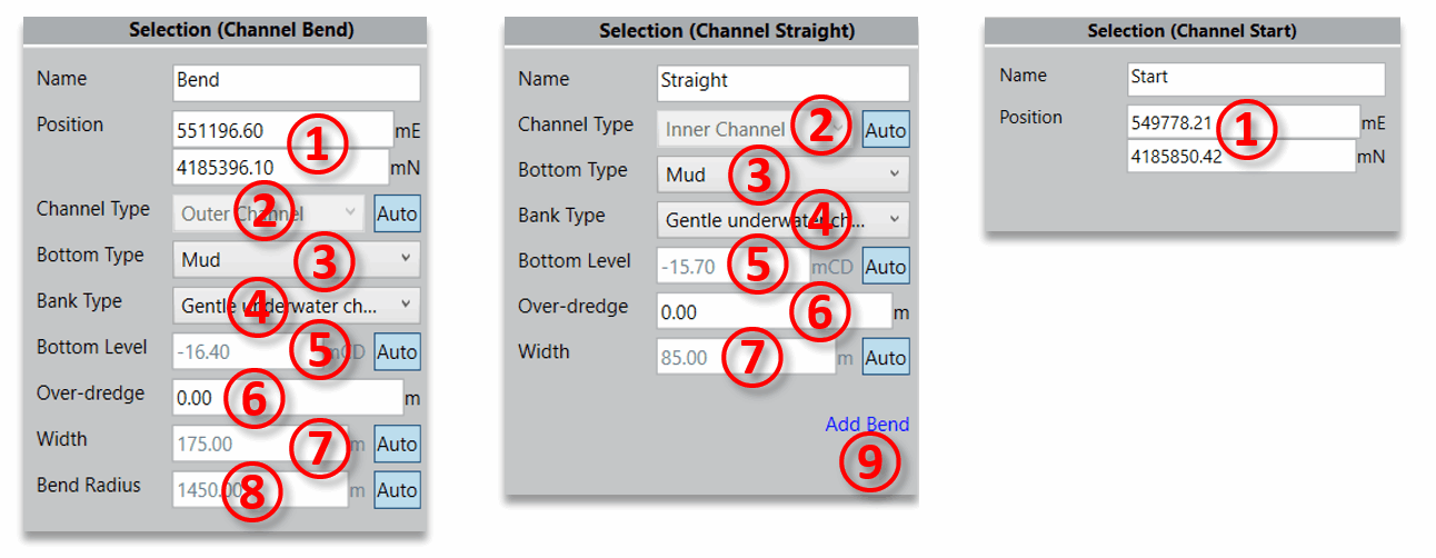
- ① Position The position in X and Y of the selected point
- ② Channel Type The type of the channel element - 'Inner' or 'Outer'. This affects the calculation of channel dimensions.
- ③ Bottom Type The material of the channel bottom - 'Mud', 'Sand/Clay' or 'Rock/Coral'. This affects the channel depth.
- ④ Bank Type The nature of the channel bank - 'Gentle underwater channel slope', 'Sloping channel edges and shoals' or 'Steep and hard embankments, structures'.
- ⑤ Bottom Level The minimum bottom level for the channel.
- ⑥ Over-dredge The over-dredging that is required beneath the minimum bottom level. This is usually added for construction tolerances and/or allowance for siltation.
- ⑦ Width The width of the channel element.
- ⑧ Bend Radius The radius of the channel bend
- ⑨ Add Bend Click this button to add a bend in the middle of a straight section of the channel.