Images showing the design area can be exported to several file formats, including .bmp, .jpg, and .png. These images can display the shaded terrain and platforms, and can optionally include grid lines, colour keys and contour lines.
To export an image, click on File, Create Drawing and then Image. The export window will appear, like the one shown below.
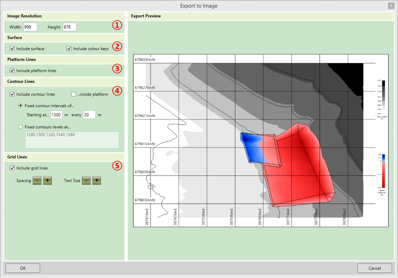
The export options on this form are described below:
- ① Image Resolution: Higher quality images then the resolution can be obtained by increasing the resolution, but it will take longer to generate the image and the file size will be larger. Note that the aspect ratio of the export image is fixed, so adjusting either the width or the height will update the other dimensions automatically.
- ② Surface: You can indicate whether or not you want to include the shaded surfaces in your export. If included, you can also choose whether or not to include colour keys beside the image. If you choose to include surfaces then the shading in the export will be the same as in the main window.
- ③ Platform Lines: Indicate whether or not the platform slope lines should be included in the image export.
-
④ Contour lines: Define options. In the first
two checkboxes, you can indicate whether you want to include contour lines in the export
image. If included, you can choose whether or not contour lines should be shown inside the
platforms; otherwise they will only be shown on the existing terrain. If contour lines are
to be drawn, you must also specify which level the lines should be drawn at, using one of
the following methods:
- Fixed Contour Intervals of... If this option is selected, contour lines will be shown with fixed intervals (e.g. every 20m). You can also specify a level to start the contour lines from. Use this to ensure a contour line is drawn at a particular level, such as 0m. Note that contour lines will be drawn both above and below this starting line at the specified interval to cover all of the ground.
- Fixed Contour Levels at... If this option is selected, the levels of each contour line can be specified by typing into the box, allowing for contour lines to be drawn at irregular intervals. Contour level values which are typed must be separated by a comma.
- ⑤ Grid Lines: In the first check box specify whether or not you want grid lines to be included. If grid lines are to be included, then the grid line spacing and the text size for grid lines can be increased or reduced by clicking on the + and - buttons.
Once the export settings have been finalised, click OK. You will be prompted for the location to save the export file and the file format to save.
Notes on 3D View Images : The image export can only produce images in the design view. To export an image of the project in one of the 3D views it is best to use the Windows Snipping Tool after putting the program into Presentation Mode. Within the program, switch to one of the 3D views and navigate to the position you want. Then, from the Display menu, select Presentation Mode. Use the windows snipping tool to take a screen capture of the area that you want and then exit presentation mode by hitting the Esc key. For instruction on how to use the Snipping Tool, refer to Windows Support: Use Snipping Tool to capture screenshots.

|
Image export customisations are discussed in our Exports - Images video, with a demonstration of capturing 3D views using the Windows Snipping Tool later in the video. |