Most existing surfaces are defined by points or contour lines. Break-lines are sometimes used in the existing to define hard edges along existing buildings, roads, etc. Tracing elevations from a site plan is a workflow that has been around since the very earliest volume estimating software. Early software required input from specialist digitisers and then later with on-screen take-off. It is still possible to trace existing elevations in this way and in fact is a skill that all users need to master. However, with the right data there are much faster ways of defining existing by importing directly from files. Options for defining elevations in the existing are listed below with full descriptions following thereafter:
Option 1: Importing from Point Files (.xyz, .csv, .txt)
Option 2: Importing from CAD Files (.dwg, .dxf)
Option 3: Importing from PDF Vectors (.pdf)
Option 4: Tracing from Site Plans
Option 1: Importing from Point Files (.xyz, .csv, .txt):
Point files are created during a topographic survey. They are a very simple format consisting of a text file with X,Y and Z co-ordinates separated by a special character (e.g. a comma). They can be imported into a 'Feature Surface' by selecting the 'Point' tab and selecting ‘Add from File’. Using point files is very fast and accurate as the points are usually raw survey data. However, the point files do not support break-lines meaning that detail in regard to hard edges cannot be imported efficiently.
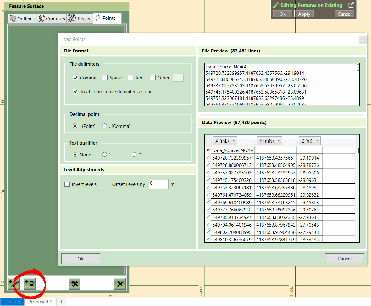
An existing surface being created from a point file
Option 2: Importing from CAD Files (.dwg, .dxf):
CAD files can contain all the necessary data to create a detailed surface in a few clicks. They may contain points, breaks, boundary outlines and contours. Within a CAD file, you can logically separate different entities into their own layers so you can have the contours in ‘Proposed Contours’ and ‘Existing Contours’, making it easy to select what you need during the import process.
However, even though a CAD file has the potential to perfectly describe a surface with contours, points and breaks, there is no guarantee this will be the case. Various issues in a CAD file can make importing difficult. For instance, entities may be enclosed in a block, contours being represented by dashes, or entities may lack Z values, causing them to be imported at 0 (zero) elevation. Kubla Cubed provides tools to resolve these problems, and in general, a CAD file is usually the optimal file format to work with.
To extract vector data from a CAD file in Kubla Cubed:
- Adding the CAD File as a Site Plan:
- Open Kubla Cubed and navigate to Plans → Add CAD File (.dwg, .dxf).
- Choose the desired CAD file and click ‘Open’.
- Scaling and Positioning the CAD File:
- CAD files are usually scaled; however, a quick scale check by holding down the 'M' button is recommended. See Quick Measure Tool.
- Selecting Elements and Adding Features:
- Click + button in Elevations and select elevation element type you wish to add.
- Choose the feature tab (Outlines, Contours, Breaks, Points) for importing.
- Click the 'Add from File' button located at the bottom-left of the editor panel.
- Select the embedded CAD file you previously added as a site plan.
- Import Entities:
- A new window will open, click ‘New Filter’
- Position the cursor, left-click to start and finish highlighting the element you want to import.
- The selected lines/points will display in the ‘Extracted’ window
- Use the options at the top of the window to filter the extracted data to your requirements.
- Repeat step 5 as required.
- Click 'Finish'.
For more details on the import window, see Adding Features from a PDF/CAD File
- Edit Entities
- Outlines, Contours and Break lines, can be edited with the editing tools, found in the Tool Menu (Hammer/Spanner), use these when you need to Join, Split, Set Multiple Elevations and Order your features. See Editing Tools.
However, there are instances when processing CAD data takes so long to process it may be easier to revert to tracing from the site plans.
Option 3: Importing from PDF Vectors (.pdf)
Unlike CAD files, PDF files do not contain technical metadata and are a poor option for transferring geo-technical information. However, their widespread use in the industry is due, in part, to the fact that they can be read by anyone without a CAD software product. For this reason, there is a benefit to being able to extract vector data directly from PDF files, as PDF files contain vector information. If this data can be extracted it can save a lot of time in tracing.
To extract vector data from a PDF file in Kubla Cubed:
- Adding a PDF File as a Site Plan:
- Open Kubla Cubed and navigate to Plans → Add PDF File (.pdf).
- Choose the desired PDF/CAD file and click ‘Open’.
- Scaling and Positioning the PDF File:
- Since PDFs are in printer space, you must scale and position the file as required.
- Use the Kubla Cubed tools to adjust the scale and position of the PDF accurately. SeeSetting the Position and Cropping.
- Selecting Elements and Adding Features:
- Click + button in Elevations and select elevation element type you wish to add.
- Choose the feature tab (Outlines, Contours, Breaks, Points) for importing.
- Click the 'Add from File' button located at the bottom-left of the editor panel.
- Select the embedded PDF file you previously added as a site plan.
- Importing Entities:
- A new window will open, click ‘New Filter’
- Position the cursor, left-click to start and finish highlighting the element you want to import.
- The selected lines/points will display in the ‘Extracted’ window
- Use the options at the top of the window to filter the extracted data to your requirements.
- Repeat step 5 as required.
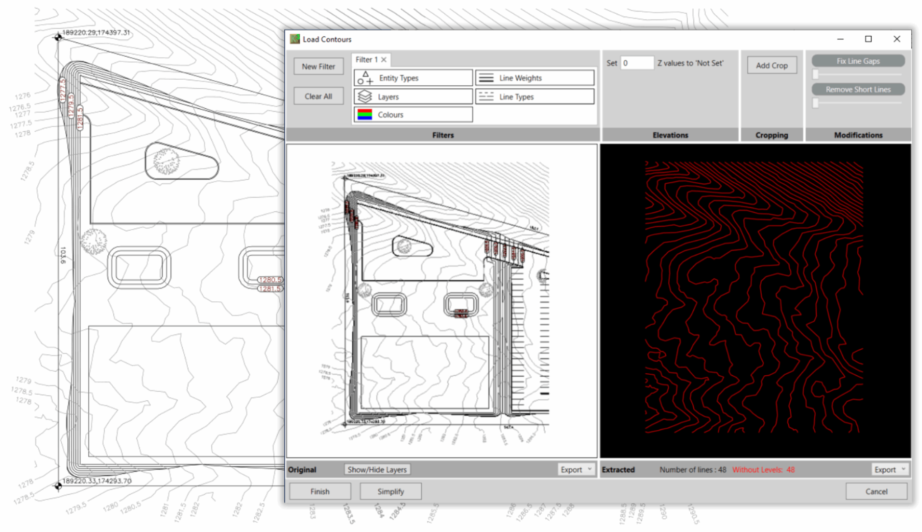
Contour lines extracted from a vector PDF file
For more details on the import window, see Adding Features from a PDF/CAD File
5. Edit Entities
- Outlines, Contours and Break lines, can be edited with the editing tools, found in the Tool Menu (Hammer/Spanner), use these when you need to Join, Split, Set Multiple Elevations and Order your features. See Editing Tools.
However, there are instances when extracing PDF vector data takes so long to process it may be easier to revert to tracing from the site plans.
Option 4: Tracing from Site Plans
Tracing elevation features from site plans can be very slow, however, there are some situations where there are no alternatives and so it can be used as the method of last resort. For instance, if the site plan is a very poor-quality scan or a CAD file does not contain data compatible with Kubla Cubed’s data importer, than tracing is a good alternative.
As an estimator you can choose to be selective in regard to what data to trace. For instance, if there are many contours you could decide to only take off every other one or even just the major contours. However, this decision comes down to the estimator's judgement as to whether the increased accuracy of the extra data is worth the extra time in tracing it all.