Most site plans do not have the subgrade level marked. Instead, they mark the final finished level (FFL) and have a separate plan of surface material thickness. When estimating bulk earthworks, we need to calculate to the subgrade, so we need to find a way of adjusting for the subgrade in our project.
Notes on Terminology : In some areas of the world, the term 'subgrade' is used, and in others 'formation level'. There are also several different terms used to refer to the level you will be standing on when the project has finished : 'finished floor level', 'finished grade' and 'final floor level' are all used.
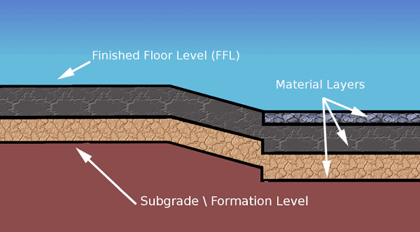
There is one issue that needs to be considered before starting, and that is how to approach the problem of elevations being marked at FFL level on a site plan (this is almost always the case). In the bulk earthworks phase, you will want to calculate to the formation/subgrade level not the FFL level, so we need some way of making these adjustments. In general there are three approaches :
1. The calculator method (not recommended)
This method involves manually adjusting elevations using a calculator before input. This works, of course, however, it is flawed. Imagine adjusting 30 contour lines by 600mm only to be told later that, after consideration, the engineer has decided to use a different build up and changes it to 700mm. Going back and adjusting with a calculator again is very time-consuming. The other issue with this method is that the elevations you look at on the plan don't match those you input, which makes it hard to check. We therefore recommend two alternative methods.
2. The Offset Method
The Offset Method is named such because we use the Z offset value that is available in all explicit absolute elements to offset an element with a negative value to make the required adjustment to the finished level. The Offset options found in the dropdown are 'Off,' 'Z', or it allows you to offset the entire surface in 'XYZ'.
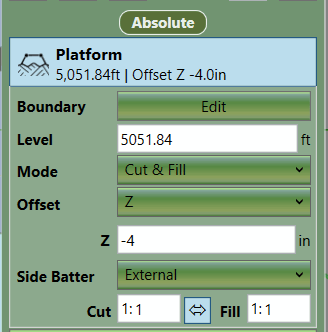
This Offset Method works very well when the different areas of material thickness are represented by different elements in a project. For instance, if you have four building pads represented by four Platforms and a car park represented by a 'Feature Surface', it is easy to offset each 'Platform' and the 'Feature Surface' to adjust for different material thickness values. However, if the car park had different material thickness values across its surface, we would run into a problem as there is only one Z offset box for the entire Feature Surface. We could split it up into different chunks, but this can be awkward. Therefore, in this scenario the 'Reduce Method' can be used to work around the problem.
3. The Reduce Method
The 'Offset Method' for adjusting FFL levels works well in most circumstances; however, there are scenarios where you run into difficulties. On some site plans, it can be difficult to break the proposed into different material areas. Typically, this is the case when the proposed is defined by a single set of elevation features (contours lines or a point cloud). Breaking the proposed into different elements to cover different material thickness in this scenario can be awkward and lead to undesirable results at the boundaries of the different elements. As the contour lines or point cloud were not intended to be broken up, you can end up with large step-downs or jagged edges in the terrain. You can often fix this by adding more elevation features along the boundary, but another approach is to use the 'Reduce Method' as opposed to the 'Offset Method'.
The 'Reduce Method' involves putting all the proposed elevations at FFL into a single 'Feature Surface'. You can actually use a number of absolute elements (Platform, Slope, etc.) but in a simple setup, a single 'Feature Surface' is used. Once you have finished defining the FFL levels in your absolute element, you then layer 'Reduce' elements over the top of the Feature Surface to adjust different areas by different material thicknesses.
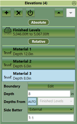
'Reduce' elements that intersect will override each other if 'Depths From' is set to ‘Auto’. The lower reduce element in the list will take precedence in the area of intersection. It is not recommended to change the setting from ‘Auto’ when using the ‘Reduce Method’ to adjust FFL levels as it is set perfectly to adjust lower FFL elements.
If following the ‘Reduce Method’ there are certain key rules you need to follow:
- 'Reduce' elements must be in the same phase as the elements that define the finished level.
- The 'Reduce' elements must be below the finished level elements in the calculation order.
- Usually the 'Reduce' elements have a very steep side batter (e.g. 0.01 or ‘Off’).
- The 'Reduce' elements should have ‘Depths From’ set to ‘Auto’.
The ‘Reduce Method’ is, in some ways, simpler than the 'Offset Method'; however, surfaces created using the ‘Offset Method’ can utilise the powerful side batter creation functionality in Kubla Cubed to create nice joins between different areas. With the ‘Reduce Method’ you have to create these side batters yourself with break-lines, contours and points. You can partially overcome this by using a number of absolute elements to define the FFL levels for areas that can be separated (e.g. building pads, parking lots etc...).

|
The Adjusting to Subgrade / Formation Level video covers adjusting FFL levels to the subgrade using the offset and reduce methods. |